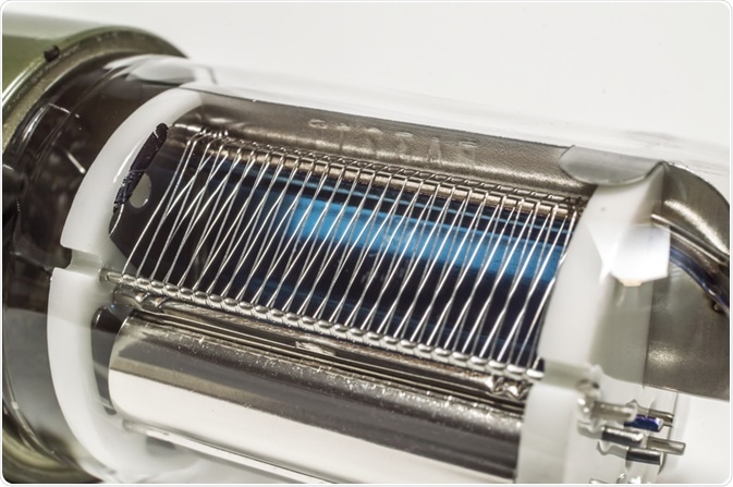
Flow cytometers use photodetectors to convert the light of excited fluorophores into photocurrent, which can be digitized. Photomultiplier tubes are one of the most common types of photodetectors used in flow cytometry and are often preferred over other common photodetectors due to their increased sensitivity.

Image Credit: Dr. Me/Shutterstock.com
How photomultiplier tubes work
Photomultiplier tubes use cathodes and anodes set in a cold vacuum tube to generate photocurrent from the light generated by the flow cytometry. The photon, generated by the excitation of the fluorophore in the sample, collides with a photocathode when entering the photomultiplier tube. This results in the creation, also known as photoemission, of electrons.
The electrons generated by the photocathode move between the dynodes that are placed cascading down the photomultiplier tube. The movement between the dynodes, which are also called electrodes, results in the generation of secondary electrons. This, in turn, leads to the signal being amplified.
In general, photomultiplier tubes are employed when the light scatter is perpendicular, rather than forward light scatter. They can also be effective when only low levels of light are emitted, as can be the case with fluorescence.
How photomultiplier tubes can be optimized
The success of photomultiplier tubes is heavily dependent on how it is set up. One of the more common optimizations that can be done on a photomultiplier tube is that of the voltage that is supplied to the flow cytometer during the process.
The sensitivity of a photomultiplier tube is dependent on the amount of voltage that is supplied, which requires optimization specific to flow cytometer machines and configurations. The Peak 2 method is generally applied for this optimization, in which a dim fluorescent particle is tested across a range of voltage settings. This can also be called a voltration.
The spread of the signal during the voltration, which is more commonly known as the coefficient of variation, is plotted over the range of voltages to figure out the best voltage. The best voltage is located at what is called the ‘inflection point’. This is the point in the graph at which the percentage of the coefficient of variation is as low as it can be while maintaining the lowest possible voltage setting.
Another way photomultiplier tubes can be optimized is based on their composition. Whereas most photodiodes (another type of photodetector) are made of silicon, photomultiplier tubes are more variable. A photomultiplier tubes’ sensitivity to a wavelength of light depends strongly on the material the photomultiplier tube is made out of.
Benefits and limitations of photomultiplier tubes
As mentioned, the voltage optimization influences the sensitivity of the flow cytometer via the responsivity of the anode. The supply voltage is typically in the 300 to 800 V range and can yield an anode responsivity of around 105 A/W. However, increased gain (the number of electrons generated by the dynodes) is also accompanied by increased photodetector noise. While the ideal experiment would be noiseless and have a noise figure of 1, most photomultiplier tubes have excess noise figures of around 1.2 to 1.4.
The presence of the dynodes amplifies the signal and is the chief reason that photomultiplier tubes are more sensitive to lower levels of signal than other photodetectors. The amplification from one single photon can result in many million times stronger energy. Other photodetectors, such as photodiodes, rely on signal amplification after the current has been generated, rather than in the process. However, this is not always a limitation, as experiments have shown that avalanche photodiodes can be complemented with external amplification to match the gain and output impedance of a photomultiplier tube.
Despite this, other photodetectors are sometimes preferred compared to photomultiplier tubes. Avalanche photodiodes have increased detection efficiency over the 400 nm to 1100 nm wavelength range than photomultiplier tubes (photomultiplier tubes have overall limited detection efficiency above 800 nm). However, this is countered by that most avalanche photodiodes have lower gain than photomultiplier tubes because increased gain leads to higher signal to noise response.
Similarly, photomultiplier tubes can have lower noise than other comparable photodetectors, but this can be offset in certain situations. Avalanche photodiodes have higher dark noise and higher gain noise than photomultiplier tubes, but avalanche photodiodes also have higher quantum efficiency which can offset this drawback. Whereas photomultiplier tubes have an excess noise factor a factor of 2 smaller than avalanche photodiodes, avalanche photodiodes can have a quantum efficiency four or more times larger than that of a photomultiplier tube.
Sources
- Piatek, S., and Hergert, E., 2018. Photodetectors In Flow Cytometers. [online] Photonics.com. Available at: <https://www.photonics.com/Articles/Photodetectors_in_Flow_Cytometers/a64058>
- Thermofisher.com. 2020. Optics Of A Flow Cytometer. [online] Available at: <https://www.thermofisher.com/au/en/home/life-science/cell-analysis/cell-analysis-learning-center/molecular-probes-school-of-fluorescence/flow-cytometry-basics/flow-cytometry-fundamentals/optics-flow-cytometer.html>
- Lawrence, W., Varadi, G., Entine, G., Podniesinski, E., and Wallace, P., 2008. A Comparison of Avalanche Photodiode and Photomultiplier Tube Detectors for Flow Cytometry. In: The International Society for Optical Engineering. The International Society for Optical Engineering.
Last Updated: Sep 8, 2020

Written by
Sara Ryding
Sara is a passionate life sciences writer who specializes in zoology and ornithology. She is currently completing a Ph.D. at Deakin University in Australia which focuses on how the beaks of birds change with global warming.
Source: Read Full Article
